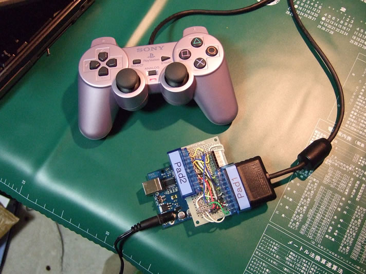
This is an example of a hardware built to work with the Playstation2 controller interfacing library for Arduino downloadable from this site.
The easiest way to connect the PS2 controller to an Arduino maybe to simply chop off the connector and hook up bare wires.
However, it may be a better idea to get hold of a socket from other hardware.
In my case, I used a PS controller<->USB adaptor I had not used in a while.
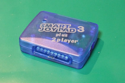 Before
For this procedure, a solder vacuum may come in handy, or maybe even manditory depending on the hardware you are disassembling.
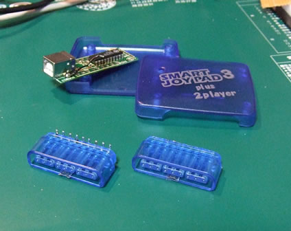 After
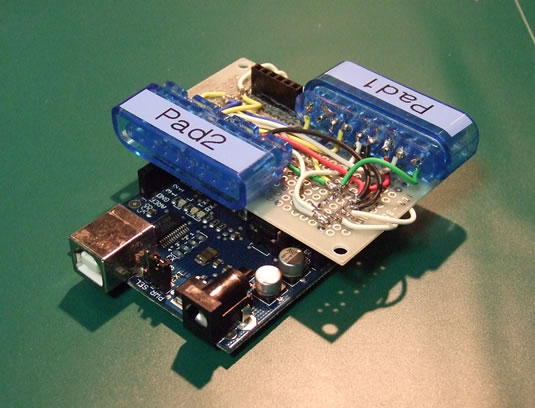
AfterHere is a photo hinting the board size and pin header layout convenient to use with my library.
The smaller group of pins will mount on the power related pins. The larger group connects to digital pins 0 through 7 on the Arduino board.
Since I plan to use the serial I/O for MIDI control, +5V, GND and TX, RX are extended through the pin socket seen in the photo.
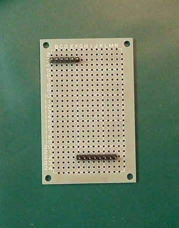
It was quite time consuming to mount 2 sockets on a board of this size.
Unless you have specific plans to use two controllers simultaneously, it may be easier to just mount one.
Also it would had been a better idea to plan extra space to place a reset button.
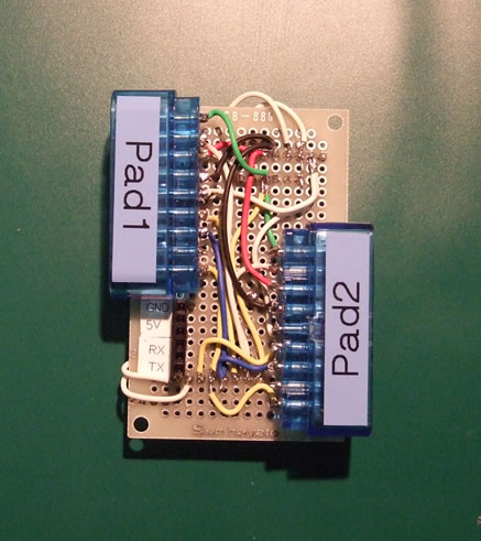
Here is a photo of the shield completed.
In addition to what you see here, there is also a 1k ohm resister array placed beneath the board to pull-up the controller pins 1 and 9.
All other technical issues are mentioned in the document attached to the library.
The copy of this document placed on the remaining of this page is NOT guaranteed to be the latest.
Playsation2 controller interface library for Arduino. (Document revised Oct. 26, 2008) by Studio Gyokimae (gyokimae at hotmaildotcom) This is my first C/C++ program. Any kind of feed back sent tois appreciated :-) ********* * Index * ********* 1. Installing the library 2. Hardware pin layout 3. Function reference 4. Pit falls I fell into during development 5. Known issues ============================================================================== 1. Installting the library ============================================================================== Like any other Arduino library, place the files under /hardware/libraries/ and restart the Arduino IDE. ============================================================================== 2. Hardware pin layout ============================================================================== There are many good guides on how the pins are layed out. This one in particular also has a good description on the protocols used to communicate with the controllers. http://www.curiousinventor.com/guides/ps2 The pin layouts are currently hard-coded inside GPSX.c. Arduino Pin No. | PSX Controller Pin No. ----------------+------------------------ Pin 7 | Pin 1 Data Pin 6 | Pin 2 Command | Pin 3 9V for Motor (Optional) | Pin 4 GND | Pin 5 VCC (3.3V) Pin 5 | Pin 6 Attention (PAD1) Pin 4 | Pin 7 Clock | Pin 8 N/C Pin 3 | Pin 9 ACK Pin 2 | Pin 6 Attention (PAD2) - If you connect only one controller, Pin 2 can be left open. Connections to all pins other than "attention" are shared by two controllers as they are designed to respond only when its "attention" pin drops low. - You need a 9V external power source to drive the motors in DualShock controllers. If you choose to use the vibration motors, > The Arduino board must run on a 9V AC adapter. > Connect Pin 3 of the controller to the "Vin" pin on your Arduino. If you choose NOT to use vibration motord, > Leave Pin 3 on the controller disconnected. > Run the board on the power source of your choice. - The following pins require a 1k ohm pullup resister as illustrated below. * The "Attention" pins for pad1 and 2 (Arduino pins 2 & 5) * Data pin (Arduino pin 7) Vcc 5V | (1kOhm) | (Arduino Pin)----+----(Controller) *** All other pins can be connected directly to the pin sockets on Arduino. To physically connect the controller to your Arduino board, you can either chop off the connetor from one of the PS2 controllers, or take a socket from junk hardware so you can easily plug in or replace the controllers. In my case, I used a socket taken from a USB<->PS converter I had lying around. Also, when using the internal high impedacne resister in the ATmega ports instead of the external 1k ohm resister, it caused some timing issues I could not over come. ============================================================================== 3. Function reference ============================================================================== - Basically, for any function you need to specify which of the two controllers the command is ment to be received by. Use either one of the two macros, "PSX_PAD1" or "PSX_PAD2". - Key states are updated only when the function "PSX.updateState(padNo)" is called. - Changing the motor rotation speeds require two steps. First, set the state by calling "PSX.motor(
)". Changes take effect the next time you call PSX.updateState(). +------------------------+ | PSX.updateState(padNo) | +------------------------+ Poll key state padNo = PSX_PAD1 | PSX_PAD2 After calling the above function, you can use one of the following macros to get the key state. *** Check if key is pressed down *** Either an integer or zero will return. IS_DOWN_LEFT(padNo) IS_DOWN_DOWN(padNo) IS_DOWN_RIGHT(padNo) IS_DOWN_UP(padNo) IS_DOWN_START(padNo) IS_DOWN_STICK_RIGHT(padNo) IS_DOWN_STICK_LEFT(padNo) IS_DOWN_SELECT(padNo) IS_DOWN_SQUARE(padNo) IS_DOWN_CROSS(padNo) IS_DOWN_CIRCLE(padNo) IS_DOWN_TRIANGLE(padNo) IS_DOWN_R1(padNo) IS_DOWN_L1(padNo) IS_DOWN_R2(padNo) IS_DOWN_L2(padNo) *** Check if key has been pressed since last updateState() Either an integer or zero will return. PRESSED_LEFT(padNo) PRESSED_DOWN(padNo) PRESSED_RIGHT(padNo) PRESSED_UP(padNo) PRESSED_START(padNo) PRESSED_STICK_RIGHT(padNo) PRESSED_STICK_LEFT(padNo) PRESSED_SELECT(padNo) PRESSED_SQUARE(padNo) PRESSED_CROSS(padNo) PRESSED_CIRCLE(padNo) PRESSED_TRIANGLE(padNo) PRESSED_R1(padNo) PRESSED_L1(padNo) PRESSED_R2(padNo) PRESSED_L2(padNo) RELEASED_LEFT(padNo) RELEASED_DOWN(padNo) RELEASED_RIGHT(padNo) RELEASED_UP(padNo) RELEASED_START(padNo) RELEASED_STICK_RIGHT(padNo) RELEASED_STICK_LEFT(padNo) RELEASED_SELECT(padNo) *** Check if key has been released since last updateState() Either an integer or zero will return. RELEASED_SQUARE(padNo) RELEASED_CROSS(padNo) RELEASED_CIRCLE(padNo) RELEASED_TRIANGLE(padNo) RELEASED_R1(padNo) RELEASED_L1(padNo) RELEASED_R2(padNo) RELEASED_L2(padNo) *** Read value. An unsigned char (uint8_t) of a value between 0 and 255 (0x00 to 0xFF) will return. ANALOG_RIGHT_X(padNo) ANALOG_RIGHT_Y(padNo) ANALOG_LEFT_X(padNo) ANALOG_LEFT_Y(padNo) +----------------------------------------------------+ | PSX.motorEnable(padNo, Motor1Enable, Motor2Enable) | +----------------------------------------------------+ Enabling/disabling motors padNo = PSX_PAD1 | PSX_PAD2 Motor1Enable = MOTOR1_ENABLE | MOTOR1_DISABLE Motor2Enable = MOTOR2_ENABLE | MOTOR2_DISABLE +----------------------------------------------------+ | PSX.motor(padNo, Motor1OnOff, uint8_t Motor2Speed) | +----------------------------------------------------+ Changing the motor's rotation speed padNo = PSX_PAD1 | PSX_PAD2 Motor1OnOff = MOTOR1_ON | MOTOR1_OFF Motor2Speed = uint8_t between 0 to 255 (0x00 to 0xFF) This function only sets the next value. Changes will take effect on next call of PSX.updateState(). +-----------------------------+ | PSX.mode(padNo, mode, lock) | +-----------------------------+ Switching Analog/Digital modes padNo = PSX_PAD1 | PSX_PAD2 mode = MODE_DIGITAL | MODE_ANALOG lock = MODE_UNLOCK | MODE_LOCK When the mode is set to "lock", the Analog key on the controller is disabled and locked to the mode specified. ============================================================================== 4. Pit falls I fell into during development ============================================================================== Many web sites describe how the ACK pin is lowered by the controller after each byte it receives successfully. However, with the PS2 controllers, the duration of this tick is extremely short and difficult to capture via polling within a loop. After struggling for a couple of days to get the timing correct, I have switched strategies to ignoring the ACK pin and sending the bytes in order with a wait in between. This worked well, especially with another non-Sony controller I owned. The current version of this library simply reads 9 bytes. (Although I should be able to avoid this by refering to the second returned byte indicating the remaining length) ============================================================================== 5. Known issues ============================================================================== * Currently, all timings are designed to work only on PS2 controllers. PS1 controllers are designed to run at half the clock speed wihch I haven't adjusted to yet. * I actually have not tried running 2 controllers at the same time, but is expected to work theoritically.